 Talk to Sales
 Benchmarks
View scores and output across OCR models spanning many document categories.
Want to run these evals on your own documents?
Talk to Sales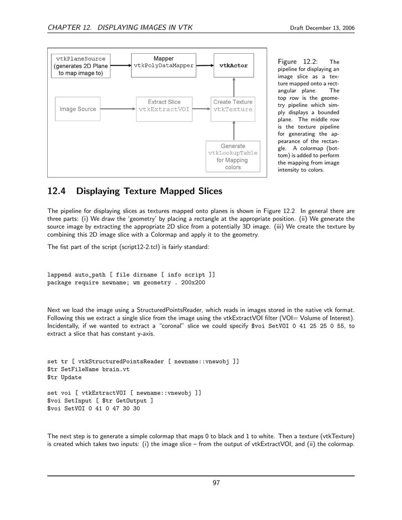
CHAPTER 12. DISPLAYING IMAGES IN VTK
Draft December 13, 2006

Figure 12.2 is a flowchart illustrating the pipeline for displaying an image slice as a texture mapped onto a rectangular plane. The pipeline is divided into three rows:
-
Top Row (Geometry Pipeline):
vtkPlaneSource(generates 2D Plane to map image to) connects toMapper(vtkPolyDataMapper), which connects tovtkActor. -
Middle Row (Texture Pipeline):
Image Sourceconnects toExtract Slice(vtkExtractVOI), which connects toCreate Texture(vtkTexture). -
Bottom Row (Color Mapping):
Generate(vtkLookupTablefor Mapping colors) connects toCreate Texture(vtkTexture).
The
Create Texture
filter receives input from both the extracted slice and the lookup table, and its output feeds into the geometry pipeline via
vtkActor
.
Figure 12.2: The pipeline for displaying an image slice as a texture mapped onto a rectangular plane. The top row is the geometry pipeline which simply displays a bounded plane. The middle row is the texture pipeline for generating the appearance of the rectangle. A colormap (bottom) is added to perform the mapping from image intensity to colors.
12.4 Displaying Texture Mapped Slices
The pipeline for displaying slices as textures mapped onto planes is shown in Figure 12.2. In general there are three parts: (i) We draw the ‘geometry’ by placing a rectangle at the appropriate position. (ii) We generate the source image by extracting the appropriate 2D slice from a potentially 3D image. (iii) We create the texture by combining this 2D image slice with a Colormap and apply it to the geometry.
The first part of the script (script12-2.tcl) is fairly standard:
lappend auto_path [ file dirname [ info script ]]
package require newname; wm geometry . 200x200
Next we load the image using a
StructuredPointsReader
, which reads in images stored in the native vtk format. Following this we extract a single slice from the image using the
vtkExtractVOI
filter (VOI= Volume of Interest). Incidentally, if we wanted to extract a “coronal” slice we could specify
$voi SetVOI 0 41 25 25 0 55
, to extract a slice that has constant y-axis.
set tr [ vtkStructuredPointsReader [ newname::vnewobj ]]
$tr SetFileName brain.vt
$tr Update

set voi [ vtkExtractVOI [ newname::vnewobj ]]
$voi SetInput [ $tr GetOutput ]
$voi SetVOI 0 41 0 47 30 30
The next step is to generate a simple colormap that maps 0 to black and 1 to white. Then a texture (
vtkTexture
) is created which takes two inputs: (i) the image slice – from the output of
vtkExtractVOI
, and (ii) the colormap.
97