 Talk to Sales
 Benchmarks
View scores and output across OCR models spanning many document categories.
Want to run these evals on your own documents?
Talk to Sales Page 1 of 1
Planar Figures of Solid Objects 投影与制图
3.1

Figure 3-3 illustrates orthographic projection. Two examples (1) and (2) show a 3D object F projected onto three mutually perpendicular projection planes: the horizontal plane
, the frontal plane
, and the profile plane
. The resulting orthographic projections are labeled
(on
),
(on
), and
(on
).
图 3—3
面图虽然直观性差些,但是度量性很好,能客观地呈现空间图形在多个方向上的度量大小,为此该方法在工程技术和机械制造方面被广泛应用。

Figure 3-4 shows the unfolded orthographic views corresponding to the 3D objects shown in Figure 3-3. (1) shows the three views (
,
,
) of the object in Figure 3-3(1) after unfolding the projection planes
,
, and
into a single plane. (2) shows the three views (
,
,
) of the object in Figure 3-3(2) similarly unfolded.
图 3—4
图 3—3 中的空间图形也可用两个投影面唯一地表示。
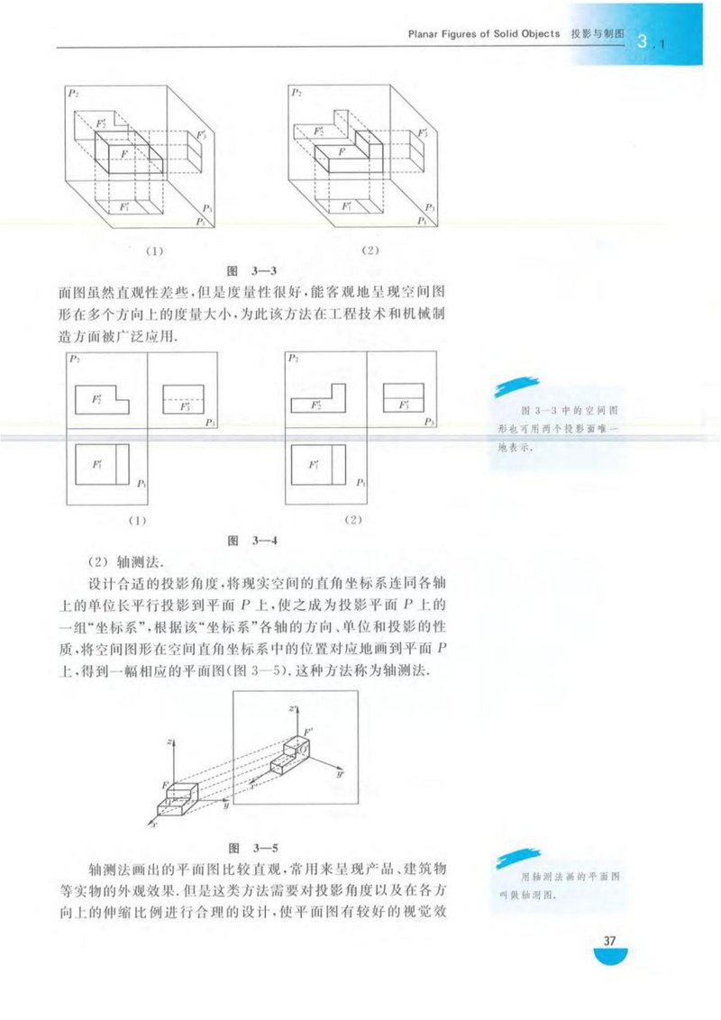
(2) 轴测法。
设计合适的投影角度,将现实空间的直角坐标系连同各轴上的单位长平行投影到平面 上,使之成为投影平面 上的一组“坐标系”,根据该“坐标系”各轴的方向、单位和投影的性质,将空间图形在空间直角坐标系中的位置对应地画到平面 上,得到一幅相应的平面图(图 3—5)。这种方法称为轴测法。

Figure 3-5 illustrates the axonometric projection method. A 3D object F is placed in a right-handed Cartesian coordinate system (x, y, z). The object and the coordinate system are projected onto a plane using parallel projection, resulting in the axonometric view
and the projected coordinate axes
,
, and
.
图 3—5
轴测法画出的平面图比较直观,常用来呈现产品、建筑物等实物的外观效果,但是这类方法需要对投影角度以及在各方向上的伸缩比例进行合理的设计,使平面图有较好的视觉效
用轴测法画的平面图
叫做轴测图。
37