 Talk to Sales
 Benchmarks
View scores and output across OCR models spanning many document categories.
Want to run these evals on your own documents?
Talk to Sales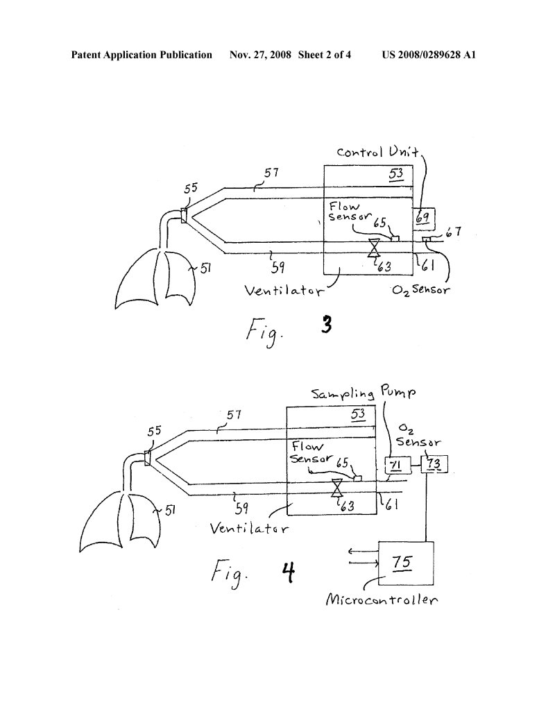
Patent Application Publication
Nov. 27, 2008 Sheet 2 of 4
US 2008/0289628 A1

Diagram illustrating a ventilator system (Fig. 3). The system includes a Ventilator (59) connected to a patient (51) via a connector (55) and flow path (57). The flow path contains a valve (63) and a Flow Sensor (65). An Sensor (61) monitors the gas. A Control Unit (53) receives input signals from the Flow Sensor (65) via line (69) and the Sensor (61) via line (67).
Fig. 3

Diagram illustrating an alternative ventilator system (Fig. 4). The system includes a Ventilator (59) connected to a patient (51) via a connector (55) and flow path (57), which contains a valve (63) and a Flow Sensor (65). A unit (53), labeled Sampling Pump, interacts with the flow path and the Flow Sensor (65). Gas is sampled from the flow path (indicated near 61) and routed to a Sampling Pump (71). The sampled gas is then measured by an Sensor (73). The output of the Sensor (73) is connected to a Microcontroller (75), which also interacts with the unit (53).
Fig. 4